Steel Detailing: What Engineers Need to Know
What structural steel detailing is, the shop and erection drawings it produces, and what the detailer needs from the engineer of record to get them right.

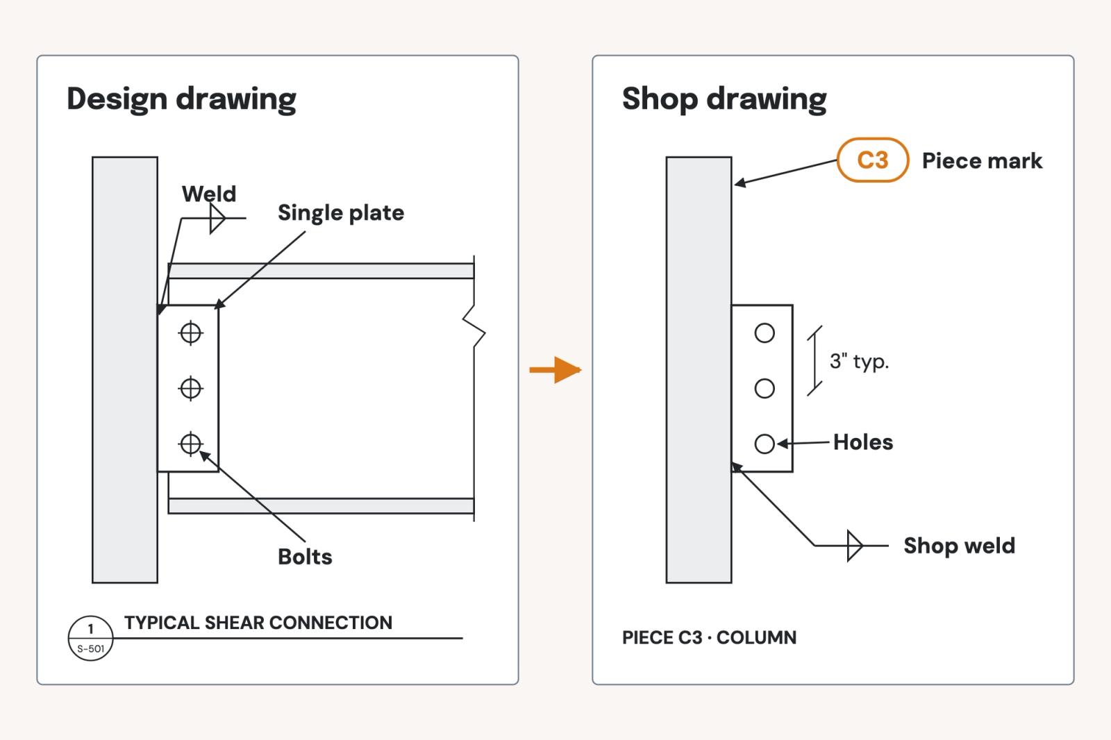
Steel detailing turns the engineer of record's design drawings into the shop drawings that a fabricator builds each piece from, and into the erection drawings crews use to put the frame together. A detailer working for the fabricator does it, usually in a 3D model. The engineer reviews the result, and the detailer can only be as exact as the design set.
This guide is written from the engineer's side of that handoff: what detailing produces, who answers for what, what to put on your drawings, and what your approval stamp means.
What steel detailing produces
Steel detailing produces the approval documents: the drawings or models the fabricator submits for your review before any steel is cut. AISC's Code of Standard Practice names four kinds.
- Shop drawings show each shipping piece as the shop will make it: lengths, holes, copes, plates, welds and bolts, under a piece mark.
- Erection drawings show where each piece goes on site and how it attaches, with the field bolts and welds.
- Embedment drawings locate the anchor rods and embedded plates that other trades set in concrete before the steel arrives.
- Fabrication and erection models can replace the drawings, or sit alongside them, when the contract says so.
The detailer also produces the bills of material and bolt summaries the shop orders from. Detailing moved from drafting boards to 2D CAD long ago. Today a detailer typically builds a 3D fabrication model in software such as Tekla Structures, SDS2 or Autodesk Advance Steel, and pulls the drawings from it.
Who does what on a steel job
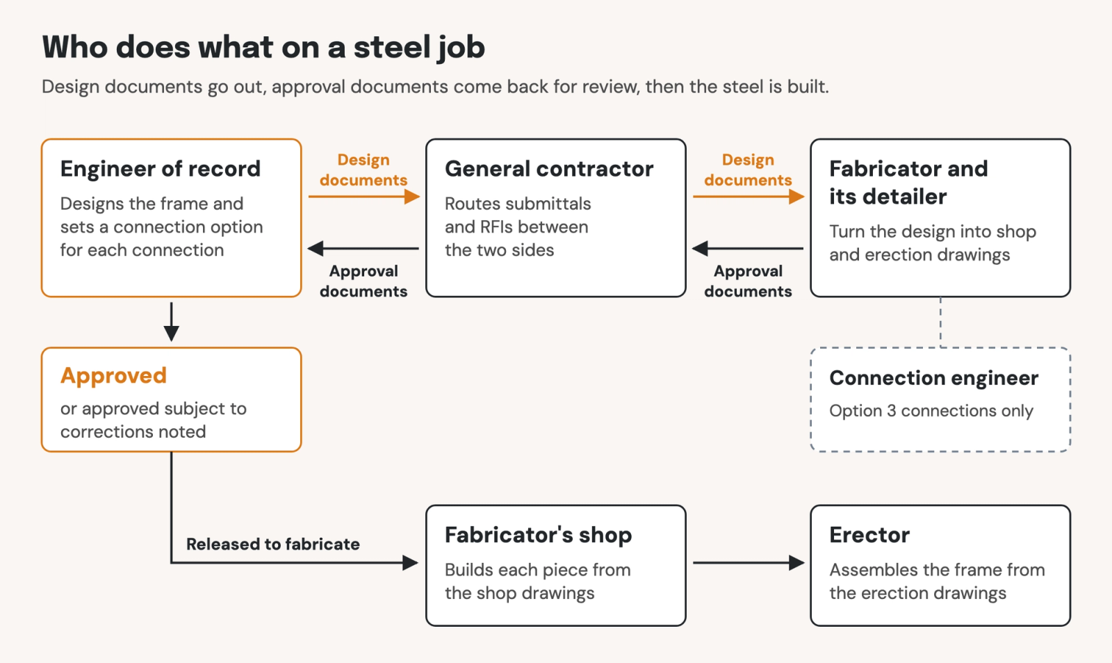
The engineer of record designs the frame, the fabricator's detailer turns it into approval documents, and the engineer approves them before fabrication starts. Around that core:
- Architect: sets the geometry the steel has to fit and the finishes, including which steel stays exposed.
- Engineer of record: designs the members and, depending on the option chosen, the connections. The Code calls this role the owner's designated representative for design.
- General contractor or construction manager: routes submittals and RFIs between the fabricator and the design team.
- Fabricator: answers for turning the contract documents into accurate approval documents, and for the dimensions that make pieces fit in the field.
- Steel detailer: produces the approval documents, on the fabricator's staff or as an independent firm the fabricator hires.
- Connection engineer: a licensed engineer working for the fabricator, when you delegate connection design.
- Erector: assembles the frame on site from the erection drawings.
Every connection needs a design option
AISC's Code of Standard Practice requires the engineer of record to designate one of three options for each connection, and that choice decides how much connection information your drawings must carry. The current edition is ANSI/AISC 303-22, Section 3.2.3.
- Option 1: the complete connection design is shown on your drawings.
- Option 2: you designate the connection to be selected or completed by an experienced steel detailer, using reference information in your documents.
- Option 3: you designate the connection to be designed by a licensed engineer working for the fabricator, who submits substantiating connection information with the approval documents.
The option is set connection by connection, so one project can use all three. For Options 2 and 3, your documents still owe the detailer the design criteria: project-specific connection details that show the concept, any limits on connection types, and the shears, moments, axial and transfer forces each connection carries. State whether Option 3 forces are service or factored, whether to use LRFD or ASD, and what substantiating information you want back.
Delegating a connection doesn't delegate the frame. Under all three options, the Code sends the approval documents back through you, and it names you as the final authority if the parties disagree about a connection's design.
What the detailer needs from your drawings
The detailer needs a complete design for the scope you release, with every dimension and requirement written down, because anything missing can result in an RFI. The Code's minimum list for contract documents, in Section 3.2.2, works as a checklist:
- Section, size, material grade and location of every member
- Geometry and work points for layout
- Column base, floor and roof elevations
- Column centers and offsets
- The lateral force-resisting system and the diaphragm elements that connect it
- Connection requirements under the option you chose, plus member reinforcement such as stiffeners and doubler plates
Drawings issued for construction add shop painting and surface preparation, the members to be treated as architecturally exposed structural steel (AESS), and leveling plate locations. Two good habits can head off a lot of questions:
- Dimension it. The Code's commentary says scaling design drawings is not accepted practice for detailing. A dimension you didn't write becomes a question.
- Make the notes match the details. Bolt, weld and material specs usually sit in the general notes. A typical detail that says something different is a discrepancy, and the Code has the fabricator report it so the design team can resolve it.
Shop drawing review: what your approval means
Approving shop drawings confirms that the fabricator read your contract documents correctly and that you accept the connections shown. It does not make the detailed dimensions or the fit-up yours: the Code keeps both with the fabricator, even after approval.
- The clock. Unless the contract says otherwise, the Code allows 14 calendar days to return approval documents to the fabricator.
- The stamp. Mark each submittal approved, or approved subject to corrections noted. Anything you can't approve goes back for revision and resubmittal.
- What to check. Member sizes and grades against your design, connections against the option and forces you set, and any connection the fabricator proposes to change. The fabricator must tell you in writing before it submits changed connection details.
- Your notes are instructions. A revision you mark on approved drawings, or give in an RFI answer, counts as released for construction. The fabricator will build it, and will flag it if it adds cost or time.
Late design changes cost the most at this stage. The Code's commentary warns that changes made after the steel is ordered will likely lead to change orders.
Where Revit fits
If you design in Revit, your model is where detailing starts, but it is rarely what the shop builds from. Revit can model steel connections, with plates, bolts and welds, so the intent shows in the model and in the views cut from it.
The detailer usually takes your model as IFC, or through a link to their own software, and rebuilds it as a fabrication model. If a design model is part of the contract documents, say whether the model or the drawings govern when they disagree; the Code expects the contract to name it. Keep the model current too: when a model is part of the design documents, the Code requires RFI answers to be carried into it.
The same connection gets drawn again on every project
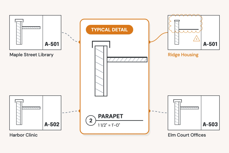
Structural firms draw the same shear tab, moment connection and base plate on project after project, and each new job starts by finding the last good version or drawing it again. Steel connections are one family of construction details, and they're illustrative of a bigger problem:
- The typicals are hard to find. They live in old project files, one office's template, or a PDF detail book.
- Offices drift apart. Two versions of the same base plate end up on two projects, and the fabricator's detailer sees both.
- Old specs travel with old details. A typical drawn before 2016 may still call for ASTM A325 bolts, a spec ASTM withdrew that year and folded into ASTM F3125 as Grade A325. Copy it forward and it ends up in an RFI log.
- RFI answers aren't applied to future projects. The answer corrects this set, but the typical that caused the question never gets updated in the firm's library. This makes it inevitable that a similar RFI will crop up on a future project.
Decide early, draw once, keep it current
The fix is mostly discipline: settle the connection decisions early and keep one current set of typical connection details.
- Choose the connection design option before the steel package goes out for pricing, and state it on the drawings, connection type by connection type.
- Keep one approved set of typical steel connection details for the firm, with an owner, and retire the versions it replaces.
- Make the general notes and the typical details say the same thing, and check both before each issue.
- When an RFI changes a typical detail, update the firm standard, not only the project.
Your firm has already drawn this connection
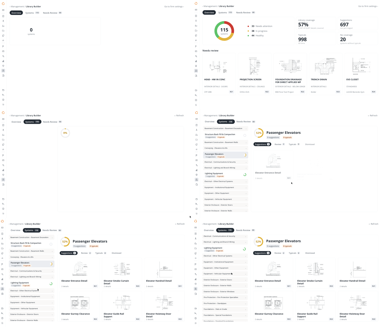
Pirros makes every detail your firm has drawn searchable, so engineers start from the last good connection instead of a blank drafting view, and the firm can mark which version is current.
Describe the condition, such as "single-plate shear connection to column web", and detail management reads the drawing itself, its geometry and annotations, rather than the file name. Promote the connections your teams repeat into firm standards: approved versions rank first in search, and outdated ones can be held to reference-only.
Buehler, a West Coast structural engineering firm, kept its standard details in a bookmarked PDF detail book before Pirros. "Managing our database of over 2,000 details is certainly easier now," says Kevin Cissna, SE, Associate Principal.
At CRAFT Engineering Studio, when a manufacturer discontinues a piece of hardware and a standard detail changes, the update goes out through Pirros and every office sees it where it already looks. See how Pirros for structural engineers covers the rest of production.
Mira handles the repetition. You approve the result.
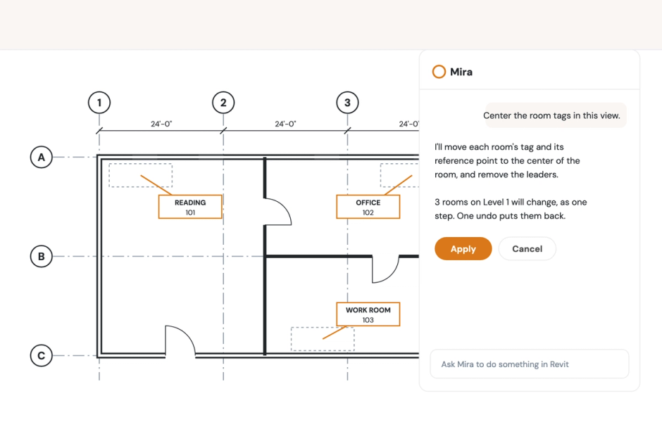
Mira, Pirros's free AI agent for Revit, works inside your model on the edits you'd otherwise make one element at a time. Three come up frequently on steel jobs.
- Renumber a typical details sheet. Type "Renumber the details on this sheet." Mira reads where each title sits, offers numbering orders including bottom-up, column by column, and points out SIM or N.T.S. numbers rather than overwriting them.
- Swap a superseded spec in every note. Type "Replace ASTM A325 with ASTM F3125 Grade A325 in every view." Mira finds every match, asks whether each note keeps its capitalization and which views to include, tells you how many notes will change, and waits for your go-ahead. It edits text notes, not keynotes or tags.
- Rebuild an old CAD typical in Revit. After you explode the import, type "Turn this CAD detail into a Revit detail." Mira redraws it to your project's own text sizes, dimension types and line weights. The steps can be found in how to convert CAD details to Revit.
Mira looks before it acts, shows a preview, and changes nothing until you approve. Most skills make their whole change as one step, so one Ctrl+Z reverses it. Mira runs in Revit 2025, 2026 and 2027.