Conduit Fill Chart: How to Use NEC Chapter 9
Sources: 2023 National Electrical Code (NFPA 70), Chapter 9 Tables 1, 4, 5 and 8, and Informative Annex C
Check your set instantlyNEC Chapter 9 Table 1 limits conduit fill to 53% of the raceway's area for one conductor. Two conductors may fill 31%, and three or more 40%. A nipple 24 inches or shorter may be filled to 60%. For mixed sizes, add each conductor's area from Table 5 and compare the total with the raceway's 40% area in Table 4.
The Pirros Quality Management System can check the conduit size of every feeder on your feeder schedules and one-lines in your set and Revit model, instantly.
How to check the code requirements
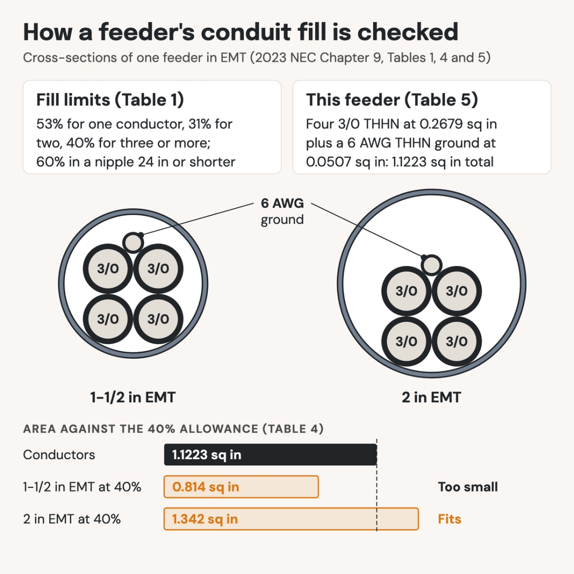
A fill chart only counts conductors of one size. A feeder with a grounding conductor of another size needs the area method. Here it is for one feeder: four 3/0 THHN conductors and a 6 AWG THHN grounding conductor in EMT.
- Count every conductor in the raceway. Grounding and bonding conductors count (Note 3). With five conductors, more than two, Table 1 allows 40% of the raceway area.
- Look up each conductor's area. Table 5 lists insulated conductors by type and size, and Table 8 lists bare ones. A 3/0 THHN conductor is 0.2679 square inches; a 6 AWG THHN conductor is 0.0507.
- Add them up. Four 3/0 conductors are 1.0716 square inches; with the 6 AWG grounding conductor, the total is 1.1223 square inches.
- Compare the total with Table 4. Find the raceway type, then the 40% column. For EMT, 1-1/2 inch allows 0.814 square inches and 2 inch allows 1.342, so this feeder needs 2 inch EMT.
- Check the ampacity before you settle the size. With more than three current-carrying conductors in the raceway, apply Table 310.15(C)(1). A larger conductor raises the total area, so run the fill check again.
- Check the run. Keep bends to 360 degrees between pull points. A nipple 24 inches or shorter may take 60% fill.
The full Chapter 9 tables and Annex C are in the National Electrical Code (NFPA 70), and the Steel Tube Institute publishes EMT fill tables. Conduit sizes sit on the feeder schedules and one-lines that MEP engineers draw, next to the other building code requirements a project's code analysis covers. That is where an AI-powered quality management system reads them.
How Pirros checks the set
The Pirros Quality Management System reviews projects against code requirements, firm standards, and project specifications, then assigns, tracks, and resolves issues before they become RFIs or rework.
- Reads every sheet in your set against the codes you pick for the project: the IBC, ADA and regional codes.
- Every finding names the sheet, the location and the section behind it.
- Findings are surfaced, never auto-applied. Your reviewer confirms, dismisses or escalates.
Requirements at a glance
| Element | Requirement | Section |
|---|---|---|
| Fill limits | One conductor: 53% of the raceway's cross-sectional area. Two conductors: 31%. Over two conductors: 40%. | NEC Chapter 9, Table 1 |
| Where Table 1 applies | Complete conduit and tubing systems. It does not apply to short sections that only protect exposed wiring from physical damage. | NEC Chapter 9, Note 2 |
| Raceway articles | Each raceway article sends its fill to Chapter 9: EMT 358.22, PVC 352.22, rigid metal conduit 344.22 and intermediate metal conduit 342.22. | NEC 358.22, 352.22, 344.22, 342.22 |
| Nipples | A nipple 24 inches long or shorter between boxes, cabinets and similar enclosures may be filled to 60%. The ampacity adjustment factors need not apply to it. | NEC Chapter 9, Note 4 |
| Grounding conductors | Equipment grounding and bonding conductors count toward fill, at their actual dimensions. | NEC Chapter 9, Note 3 |
| Mixed conductor sizes | Use the actual dimensions, or Table 5 for each insulated conductor (Table 5A for compact conductors). Compare the total with the raceway area in Table 4. | NEC Chapter 9, Note 6 |
| Bare conductors | Where bare conductors are permitted, their dimensions may come from Table 8. | NEC Chapter 9, Note 8 |
| Conductors of one size | Annex C gives the maximum number of conductors of one size and insulation per trade size. It is informative, not mandatory. | NEC Chapter 9, Note 1 |
| Rounding | When counting conductors of one size, a result with a decimal of 0.8 or more rounds up to the next whole conductor. | NEC Chapter 9, Note 7 |
| Cables and cords | A multiconductor cable, optical fiber cable or flexible cord counts as one conductor, at its overall area. | NEC Chapter 9, Note 9 |
| Heat and pulling | No more conductors than allow heat to dissipate and let them be installed or withdrawn without damage to the conductors or their insulation. | NEC 300.17 |
| Bends between pull points | 360 degrees of bends in total, at most, between pull points. | NEC 358.26, 352.26, 344.26, 342.26 |
| Ampacity adjustment | Over three current-carrying conductors in one raceway reduce each one's ampacity. The factor is 80% for 4 to 6, 70% for 7 to 9 and 50% for 10 to 20. | NEC Table 310.15(C)(1) |
| Wireways | Conductors may fill 20% of the wireway's cross-section. Splices and taps may fill 75% of it at any point. | NEC 376.22, 376.56 |
These rules are from the 2023 NEC; states adopt each edition on their own schedule, so check the one your jurisdiction enforces. The 53, 31 and 40% limits and the 60% nipple allowance carry over between editions. The ampacity adjustment table has been renumbered between editions, so match the section number to the edition you design to. Areas quoted here are the cells the worked example uses; read the full tables in NFPA 70.