Part H Building Regulations: Drainage and Waste Disposal
Sources: Approved Document H (drainage and waste disposal), 2015 edition
Check your set instantlyPart H of the Building Regulations covers drainage and waste disposal in England, with guidance in Approved Document H. A foul drain carrying a WC is 100 mm minimum, laid no flatter than 1:80 where peak flow exceeds 1 l/s. Inspection chambers sit at most 45 m apart. Building within 3 m of a mapped sewer falls under H4.
The Pirros Quality Management System can check the pipe sizes, gradients and inspection chambers on every drainage layout in your set and Revit model, instantly.
How to check the code requirements
Part H is checked on the below-ground drainage layout, the drainage details and the site plan. Building Control reads each run's label against its size, gradient and the appliances it serves.
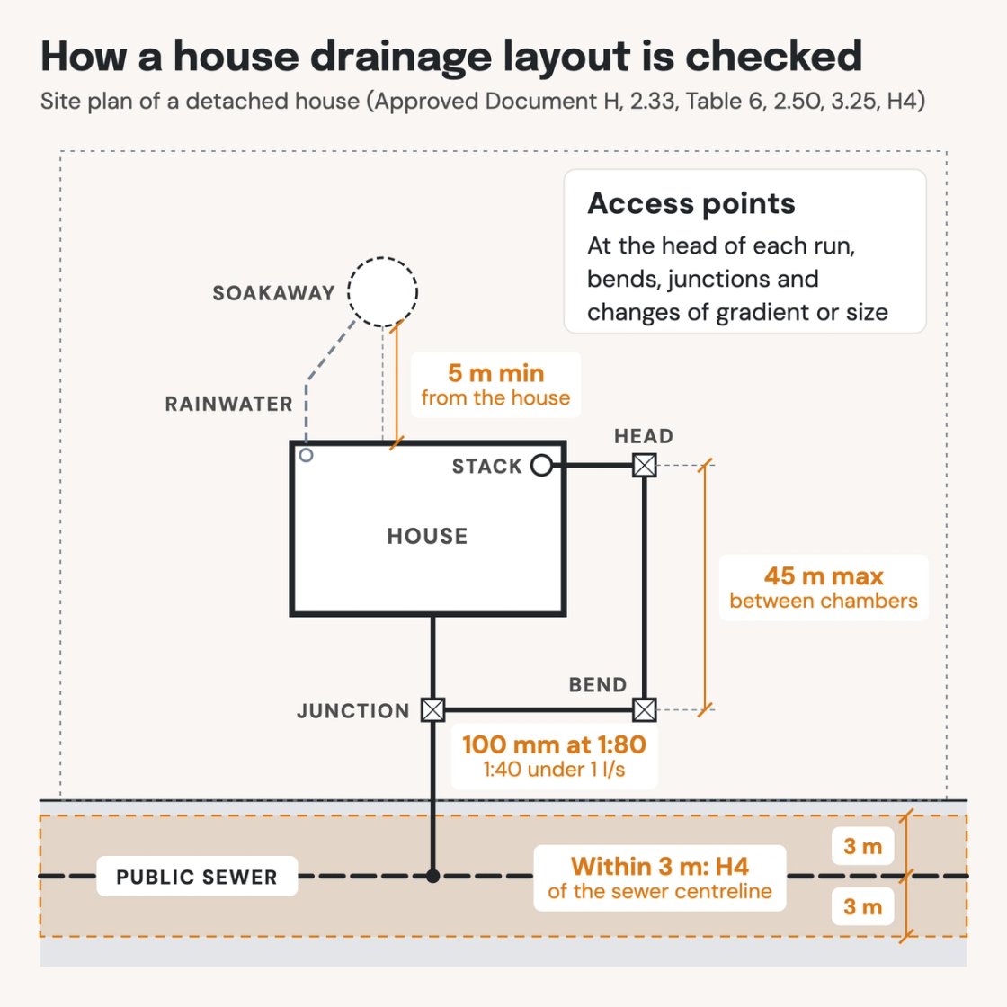
- Label every run with its size and gradient. A run carrying a WC is 100 mm minimum (H1 2.33). Check each gradient against Table 6: 1:80 for a 100 mm drain over 1 l/s, 1:40 below it.
- Place the access points. Put one at the head of each run, at bends, at changes of gradient or size, and at junctions (H1 2.49). Then measure between them against Table 13: 45 m between inspection chambers.
- Check runs at and under the building. Show the 100 mm flexible fill under the slab and how each pipe passes through a wall (H1 2.23, 2.24). Check any trench within 1 m of a foundation (2.25).
- Plot the public sewer and its 3 m zone. Take the line from the sewer records. If the building sits over or within 3 m of it, H4 applies. Nothing goes over its chambers, and the 6 m, 3 m-deep and 225 mm limits need the owner's permission.
- Dimension soakaways and septic tanks. A soakaway sits at least 5 m from the building and any road (H3 3.25). A septic tank sits at least 7 m from habitable rooms, with its drainage field 15 m from any building (H2 1.16, 1.27).
- Show the bin store and its route. Residents carry waste no more than 30 m, and the store sits within 25 m of the collection point. The route has 3 steps at most (H6 1.8, 1.10).
The full guidance, with every table, is Approved Document H on gov.uk. On a drawing set these numbers sit on the drainage layouts, sections and site plan, which is where an AI-powered quality management system reads them.
How Pirros checks the set
The Pirros Quality Management System reviews projects against code requirements, firm standards, and project specifications, then assigns, tracks, and resolves issues before they become RFIs or rework.
- Reads every sheet in your set against the codes you pick for the project: the Building Regulations and Approved Documents.
- Every finding names the sheet, the location and the section behind it.
- Findings are surfaced, never auto-applied. Your reviewer confirms, dismisses or escalates.
Requirements at a glance
| Element | Requirement | Section |
|---|---|---|
| The six requirements | H1 foul water drainage; H2 wastewater treatment systems and cesspools; H3 rainwater drainage; H4 building over sewers; H5 separate systems of drainage; H6 solid waste storage. | Schedule 1, Part H |
| Foul drain size | 75 mm internal diameter minimum. 100 mm minimum for a drain carrying WC or trade effluent. | H1 2.33 |
| Sewer size | A sewer, meaning a drain serving more than one property, is normally 100 mm minimum for up to 10 dwellings. For more than 10 dwellings, 150 mm. | H1 2.30 |
| Foul drain gradients | Peak flow under 1 l/s: 75 and 100 mm drains at 1:40. Over 1 l/s: 75 mm at 1:80, and 100 mm at 1:80 with at least one WC. 150 mm at 1:150 with at least five WCs. | H1 Table 6 |
| Gradients and bends | Even gradients, with any change of gradient at an access point. Straight runs where practicable, with bends in or close to inspection chambers or manholes, or at the foot of a stack. | H1 2.19, 2.20 |
| Rainwater drain gradients | 75 and 100 mm drains at no flatter than 1:100, 150 mm at 1:150 and 225 mm at 1:225. | H3 3.15 |
| Where access points go | At or near the head of each drain run, at bends, and at changes of gradient or pipe size. Also at junctions that can't be rodded from another access point. | H1 2.49 |
| Access point spacing | For drains up to 300 mm: 45 m maximum between inspection chambers and 90 m between manholes. From the start of an external drain, 22 m to an inspection chamber and 45 m to a manhole. | H1 2.50, Table 13 |
| Chamber sizes | An inspection chamber up to 1.2 m deep to invert is 450 by 450 mm or 450 mm diameter. A manhole on a sewer is at least 1,200 by 675 mm or 1,200 mm diameter. | H1 Table 11 · Table 12, note 7 |
| Drains under buildings | At least 100 mm of granular or other flexible fill round the pipe. Special protection where the crown of the pipe is within 300 mm of the underside of the slab. | H1 2.23 |
| Pipes through walls | A short built-in length with joints within 150 mm of the wall faces and rocker pipes of 600 mm at most either side. Or an opening with 50 mm clearance all round, masked and sealed. | H1 2.24, Diagram 7 |
| Trenches near foundations | A trench dug lower than a nearby foundation is filled with concrete. Within 1 m of the foundation, up to its lowest level; further away, to below it by the distance from the building less 150 mm. | H1 2.25, Diagram 8 |
| Stacks and vent pipes | Stacks never reduce in the direction of flow: 75 mm minimum for WCs with outlets under 80 mm, 100 mm for larger outlets. Ventilating pipes finish at least 900 mm above any opening within 3 m. | H1 1.28, 1.31 |
| Trap sizes and seals | Washbasin and bidet 32 mm with a 75 mm seal; bath and shower 40 mm with 50 mm; sink 40 mm with 75 mm. WC 75 mm for outlets under 80 mm, otherwise 100 mm, both with a 50 mm seal. | H1 Table 1 |
| Building near a sewer (H4) | Applies over or within 3 m of the centreline of a drain, sewer or disposal main on the sewer records. No building over a manhole or inspection chamber on a sewer serving more than one property. | H4 0.1, 1.3 |
| Sewer under a building (H4) | No more than 6 m of drain or sewer under a building without its owner's permission. The same applies over or within 3 m of a sewer more than 3 m deep or more than 225 mm in diameter. | H4 1.5, 1.6 |
| Foundations over a sewer (H4) | A diversion route that stays 3 m from the building. Under 2 m deep, the drain passes through the wall. Over 2 m deep, the foundation spans it as a lintel at least 1.5 m either side. | H4 1.4, 1.10, 1.12 |
| Soakaways (H3) | Not within 5 m of a building or road, in unstable land, or where the water table reaches the bottom. Designed for a 1 in 10 year return period; one serving 25 m² or less may assume 10 mm of rain in 5 minutes. | H3 3.25, 3.27 |
| Septic tanks (H2) | At least 7 m from habitable parts of buildings, and within 30 m of vehicle access where emptied by tanker. Its drainage field at least 15 m from any building, 10 m from a watercourse and 50 m from a groundwater abstraction point. | H2 1.16, 1.17, 1.27 |
| Cesspools (H2) | At least 7 m from habitable parts of buildings and within 30 m of vehicle access. At least 18,000 litres below the inlet for 2 users, plus 6,800 litres for each extra user. | H2 1.59, 1.60, 1.61 |
| Separate systems (H5) | Rainwater drainage to a sewer is kept separate from foul water where a separate surface water sewer is available. | H5 |
| Waste storage (H6) | Storage for 0.25 m³ of separated waste per dwelling, or as the waste collection authority agrees. Residents carry waste 30 m at most, excluding vertical distance, and containers sit within 25 m of the collection point. | H6 1.1, 1.8 |
| Bin store route (H6) | For containers up to 250 litres, no more than 3 steps between store and collection point, and slopes no steeper than 1:12. | H6 1.10 |
These numbers are from Approved Document H, 2015 edition, which took effect on 1 October 2015 and applies in England. The 2002 edition as amended still applies to work started, or notified, before then. The 2015 edition added solid waste guidance to H6 and changed H3's limits after Part M was amended. Wales, Scotland and Northern Ireland set their own rules.