Approved Document K (Part K): Stairs, Ramps and Guarding
Sources: Approved Document K (protection from falling, collision and impact), 2013 edition
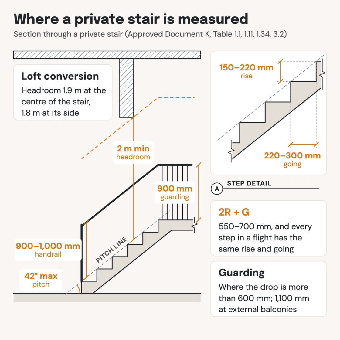
Check your set instantlyApproved Document K sets Part K's rules for stairs, ramps, guarding, glazing and doors in England. A private stair rises 220 mm at most, with a 220 mm minimum going and a 42° maximum pitch. Handrails sit 900 to 1,000 mm above the pitch line. Guarding is 900 mm on dwelling stairs and 1,100 mm at external balconies.
The Pirros Quality Management System can check the rise, going, pitch and guarding heights on every stair section in your set and Revit model, instantly.
How to check the code requirements
Most of Part K is checked on the stair sections and the plans. Building Control reads the stair category first, because a private, utility and general access stair each have their own limits.
- Name the stair category. A stair serving one dwelling is a private stair. A stair for everyone in the building is a general access stair. A stair for escape or maintenance is a utility stair (Appendix A).
- Check rise, going and pitch on the section. Divide the floor-to-floor height by the riser count. Test each rise and going against Table 1.1, and 2R + G against 550 to 700 mm. Measure the going nosing to nosing.
- Check headroom along the pitch line. Draw the 2 m line over the flight and landings and look for beams, bulkheads and the floor above. In a loft conversion, 1.9 m at the centre and 1.8 m at the side is the minimum (Diagram 1.4).
- Dimension handrails and guarding. Handrails at 900 to 1,000 mm above the pitch line; guarding at the Diagram 3.1 height for the building and location. Where children under five may be present, check balusters against the 100 mm sphere.
- Check landings and door swings on the plan. Each landing is at least the flight's width in both directions. Outside dwellings, doors don't swing across a landing; in a dwelling, a door may swing across the bottom landing as Diagram 1.8 shows.
- Mark critical glazing on the elevations. Glazing below 800 mm in walls needs safety glazing or protection. So does glazing below 1,500 mm in doors, and in side panels within 300 mm of a door (Diagram 5.1).
For the US version of these rules, see the IBC and IRC stair riser and tread limits and the US handrail rules. The full guidance is Approved Document K on gov.uk. On a drawing set these numbers sit on the stair sections, plans and elevations, which is where an AI-powered quality management system reads them.
How Pirros checks the set
The Pirros Quality Management System reviews projects against code requirements, firm standards, and project specifications, then assigns, tracks, and resolves issues before they become RFIs or rework.
- Reads every sheet in your set against the codes you pick for the project: the Building Regulations and Approved Documents.
- Every finding names the sheet, the location and the section behind it.
- Findings are surfaced, never auto-applied. Your reviewer confirms, dismisses or escalates.
Requirements at a glance
| Element | Requirement | Section |
|---|---|---|
| Private stair (one dwelling) | Rise 150 to 220 mm and going 220 to 300 mm, with a 42° maximum pitch. External tapered steps to a dwelling have a 280 mm minimum going. | Paragraph 1.3, Table 1.1 |
| Utility stair | Rise 150 to 190 mm and going 250 to 400 mm. A utility stair is used for escape, maintenance access or other purposes, not as the everyday route. | Table 1.1 |
| General access stair | Rise 150 to 170 mm and going 250 to 400 mm, for the everyday route between levels. School buildings prefer a 150 mm rise and 280 mm going. | Table 1.1, note 3 |
| Rise and going together | Twice the rise plus the going (2R + G) between 550 and 700 mm. Every step in a flight has a level tread and the same rise and going. | Table 1.1 · Paragraph 1.5 |
| Headroom | 2 m minimum over the flight and landings. In a loft conversion without room for 2 m: 1.9 m at the centre of the stair, falling to 1.8 m at its side. | Paragraphs 1.11, 1.13 (Diagrams 1.3, 1.4) |
| Stair width (buildings other than dwellings) | 1,200 mm minimum between enclosing walls, strings or upstands, and 1,000 mm between handrails. A flight over 2 m wide is divided into flights at least 1,000 mm wide. | Paragraph 1.15 |
| Risers per flight | Any stair with more than 36 risers in consecutive flights changes direction at least once. Outside dwellings: no single steps, and 12 risers maximum per general access flight (16 exceptionally in small premises), 16 per utility flight. | Paragraphs 1.17, 1.18 |
| Landings | At the top and bottom of every flight, at least as wide and long as the flight's smallest width. Landings are level and clear of permanent obstructions. Outside dwellings, 1,200 mm minimum unobstructed length. | Paragraphs 1.20, 1.22, 1.23 |
| Open risers | Allowed in dwellings if treads overlap by 16 mm minimum and a 100 mm sphere can't pass through. Not allowed in buildings other than dwellings or in the common areas of flats. | Paragraphs 1.6, 1.9, 1.10 |
| Nosings | Outside dwellings: a nosing that contrasts visually, 55 mm wide minimum on tread and riser, overhanging 25 mm at most. Common areas of flats: 50 to 65 mm on the tread, 30 to 55 mm on the riser. | Paragraphs 1.7, 1.10 |
| Handrails | Top of handrail 900 to 1,000 mm above the pitch line or floor, on both sides where the stair is 1,000 mm or wider. Outside dwellings: both sides of flights and landings, 900 to 1,100 mm high on landings, extending 300 mm minimum past each end. | Paragraphs 1.34, 1.35 (Diagram 1.12) |
| Where guarding is needed | Dwellings: at the sides of flights and landings where the drop is more than 600 mm. Other buildings and common areas of flats: at flights and landings with two or more risers. Elsewhere outside dwellings, at drops of more than 380 mm. | Paragraphs 1.40, 1.41 · K2 performance |
| Guarding height, dwellings | 900 mm at stairs, landings, ramps and internal floor edges. 1,100 mm at external balconies, Juliet balconies included, and at roof edges. | Paragraph 3.2, Diagram 3.1 |
| Guarding height, other buildings | 900 mm on flights and 1,100 mm elsewhere, in residential, institutional, educational, office, public, retail and assembly buildings. In assembly buildings, 800 mm within 530 mm in front of fixed seating. | Diagram 3.1 |
| Guarding at opening windows | 800 mm in all buildings, except roof windows in loft extensions, which follow Approved Document B. | Diagram 3.1 |
| Openings in guarding | Where children under five may use the building, a 100 mm sphere can't pass through any opening. The guarding is also hard to climb: no horizontal rails. | Paragraphs 1.39, 3.3 |
| Ramp gradient | 1:12 maximum for a 2 m going (166 mm rise), 1:15 for 5 m (333 mm) and 1:20 for 10 m (500 mm), interpolating between. A floor at 1:20 or steeper is designed as a ramp. | Paragraph 2.3, Diagram 2.1 |
| Ramps outside dwellings | 1,500 mm minimum width, handrails on both sides and a 100 mm kerb on any open side. Landings 1,200 mm long at foot and head and 1,500 mm between flights. Passing places of 1,800 by 1,800 mm where the ramp can't be seen end to end or has three or more flights. | Paragraphs 2.5, 2.9, 2.11, 2.13 |
| Glazing in critical locations | From floor level to 1,500 mm in doors and in side panels within 300 mm of a door. From floor level to 800 mm in walls and partitions. There, glazing breaks safely, is robust or in small panes, or is screened. | Paragraph 5.2, Diagram 5.1 |
| Manifestation (buildings other than dwellings) | Glass doors and glazed screens marked at two levels, 850 to 1,000 mm and 1,400 to 1,600 mm above the floor. A logo or sign at least 150 mm high, or a band at least 50 mm high. | Paragraph 7.4, Diagram 7.2 |
| Vision panels (buildings other than dwellings) | Door leaves and side panels wider than 450 mm have vision panels toward the leading edge. Zones of visibility from 500 to 800 mm and from 1,150 to 1,500 mm above the floor. | Paragraph 10.1, Diagram 10.1 |
| Vehicle barriers | At least 375 mm high at a floor or roof edge and 610 mm at a ramp edge. Barriers resist the loads in BS EN 1991-1-1 and its UK National Annex. | Paragraph 4.2, Diagram 4.2 |
These numbers are from Approved Document K, 2013 edition, which took effect on 6 April 2013 and applies in England. Wales, Scotland and Northern Ireland set their own rules. In October 2026 the Building Safety Regulator opened a 10-week call for evidence on Part K. The current guidance stays in place meanwhile, and any change would go to further consultation.