Approved Document C: Moisture, Radon and DPCs
Sources: Approved Document C (site preparation and resistance to contaminants and moisture), 2004 edition incorporating 2010 and 2013 amendments
Check your set instantlyApproved Document C covers Part C: site preparation, contaminated land, radon and moisture. A wall’s damp-proof course (DPC) sits at least 150 mm above the adjoining ground, continuous with the floor membrane. Cavities run 225 mm below the lowest DPC, or a cavity tray drains them. Suspended timber floors need a ventilated void 150 mm deep.
The Pirros Quality Management System can check the DPC height on every ground-floor wall section in your set and Revit model, instantly.
How to check the code requirements
Part C lands on the ground-floor details: the wall section at the DPC, the floor build-up and any sub-floor void. Draw one detail for each floor type. Then check each dimension against Sections 4 and 5.
- Read the site investigation first. It sets the contaminants, the ground gases and the water table that the details respond to (1.1, 2.13, 3.2).
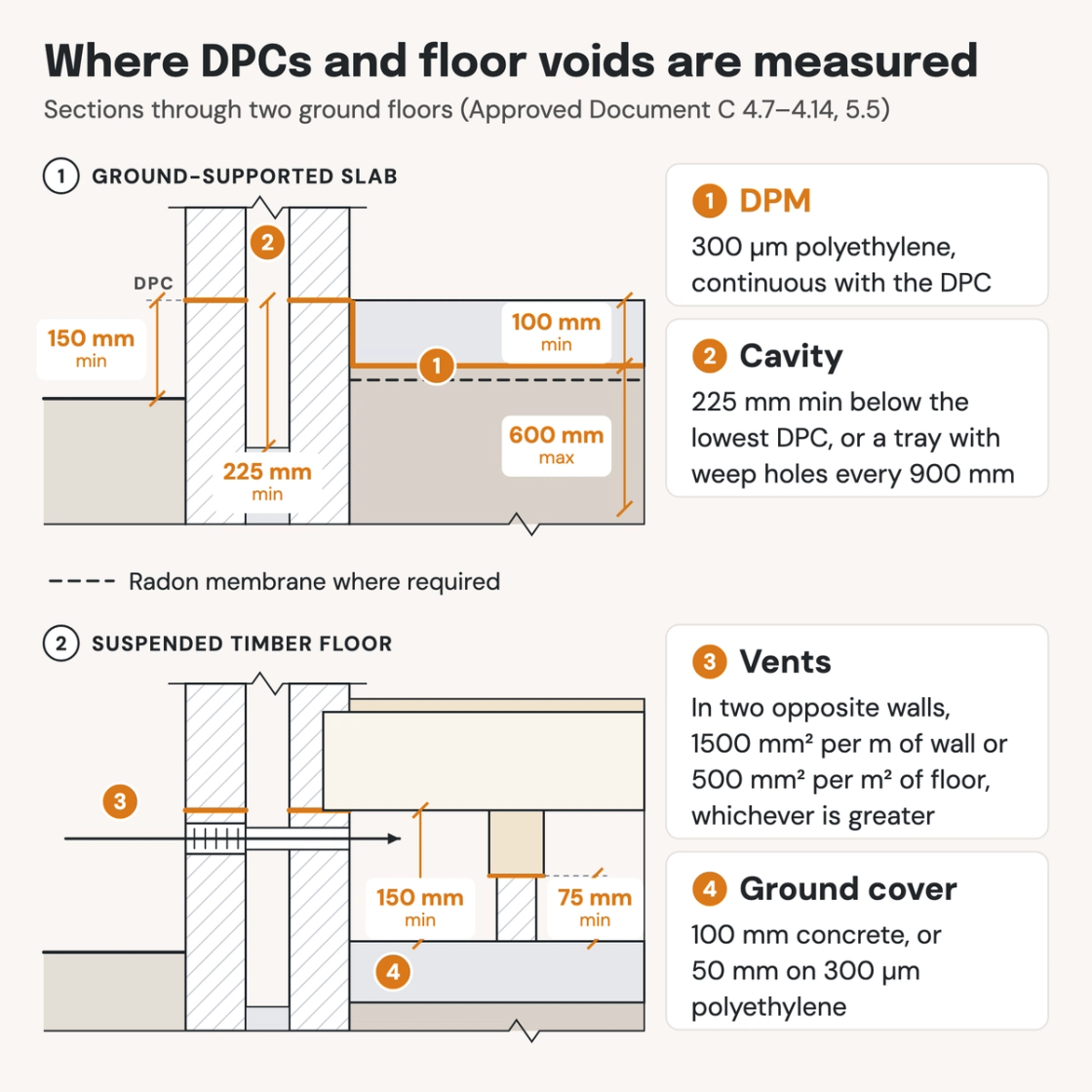
- Dimension the DPC from the outside ground. Measure the 150 mm minimum from the adjoining ground, not from the slab (5.5(b)). Check that the external levels on the site plan match the section.
- Join the membrane to the DPC. The floor’s damp-proof membrane runs continuous with the wall DPCs (4.7, 5.5(a)). Show the lap on the detail.
- Take the cavity down, or tray it. 225 mm below the lowest DPC, or a cavity tray with weep holes every 900 mm (5.5(c)). Over openings, show the stop ends and at least two weep holes.
- Size the sub-floor void and vents. 75 mm to the wall-plates and 150 mm to the floor under suspended timber (4.14). Total the vents on two opposite walls against 1500 mm² per metre run and 500 mm² per m² of floor, and use the larger.
- Mark the radon measures. Check the site against the BR 211 maps or a UKradon report (2.40). Where protection applies, show the membrane on the floor and wall details.
Where the DPC, cavity tray and floor details are still in CAD, Mira can convert CAD details to Revit. It rebuilds the detail, but doesn’t check it against Part C. Approved Document C is free on gov.uk. On a drawing set these dimensions sit on the wall section and ground-floor details. That is where an AI-powered quality management system reads them.
How Pirros checks the set
The Pirros Quality Management System reviews projects against code requirements, firm standards, and project specifications, then assigns, tracks, and resolves issues before they become RFIs or rework.
- Reads every sheet in your set against the codes you pick for the project: the Building Regulations and Approved Documents.
- Every finding names the sheet, the location and the section behind it.
- Findings are surfaced, never auto-applied. Your reviewer confirms, dismisses or escalates.
Requirements at a glance
| Element | Requirement | Section |
|---|---|---|
| Site preparation and contaminants | Clear the ground of vegetable matter, topsoil and pre-existing foundations. Take reasonable precautions against contaminants on or in the ground, including radioactive ones such as radon. Provide subsoil drainage where needed to keep ground moisture out, or to stop damage such as water carrying contaminants to the foundations. | Requirement C1 |
| Resistance to moisture | Walls, floors and roof protect the building and its users from ground moisture, rain and wind-driven spray, and condensation. They also resist spillage from sanitary fittings and fixed appliances. | Requirement C2 |
| Site investigation and clearance | Investigate the site to the extent its type of development and previous use need. Remove turf, roots and other vegetable matter deep enough to prevent later growth. | Paras 1.2, 1.4 |
| Contaminated land | A preliminary assessment of past and present uses, then a detailed ground investigation where the risks call for one. Unacceptable risks are dealt with by treatment, containment or removal. | Paras 2.10, 2.13, 2.15 |
| Methane and other ground gases | Further investigation may be needed on or within 250 m of a landfill site, among other cases. Dwellings get a gas-resistant barrier across the whole footprint over a vented extraction layer. Non-domestic buildings follow the same principles, with expert advice. | Paras 2.28, 2.37, 2.38 |
| Radon | In areas where radon may be elevated, new buildings, extensions and conversions can need protection. BRE’s BR 211 sets basic measures where 3% to 10% of homes are predicted at or above 200 Bq/m³, and full measures above 10%. A UKradon or BGS report can replace its maps. | Paras 2.39, 2.40 |
| Subsoil drainage | Drain the ground under the building, or protect it another way, where the water table can rise to within 0.25 m of the lowest floor. | Para 3.2 |
| Ground-supported floors | Compacted hardcore no more than 600 mm deep and concrete at least 100 mm thick. A damp-proof membrane runs continuous with the DPCs in the walls. | Para 4.7 |
| Damp-proof membrane | Under the slab, polyethylene at least 300 µm (1200 gauge) thick with sealed joints, on a bed that will not damage it. Over the slab, polyethylene or three coats of cold-applied bitumen solution, protected by a screed or floor finish. | Paras 4.8, 4.9 |
| Suspended timber floors | Ground cover of 100 mm concrete, or 50 mm of concrete or fine aggregate on 300 µm polyethylene. A ventilated void at least 75 mm deep to the wall-plates, and 150 mm to the underside of the floor or its insulation. | Para 4.14 |
| Sub-floor ventilation | Vents in two opposite external walls give at least 1500 mm² per metre of wall or 500 mm² per m² of floor, whichever is greater. Ventilation pipes at least 100 mm in diameter, and grilles that keep out vermin. | Paras 4.14, 4.19 |
| Suspended concrete floors | In-situ concrete at least 100 mm thick with 40 mm cover to the reinforcement, or precast construction. A ventilated void at least 150 mm deep, and a membrane where the ground below is dug lower than the surrounding ground and not drained. | Paras 4.18, 4.19 |
| Floor surface condensation | A ground floor’s U-value no worse than 0.7 W/m²K at any point, with junctions to Accredited Construction Details or BRE IP17/01. | Para 4.22 |
| Damp-proof course height | A DPC continuous with any membrane in the floor. In an external wall, at least 150 mm above the adjoining ground, unless part of the building protects the wall. | Para 5.5(a), (b) |
| Cavity below the DPC | The cavity runs at least 225 mm below the lowest DPC. Otherwise a damp-proof tray protects the inner leaf, with weep holes every 900 mm. Where a tray stops short, as over an opening, it has stop ends and at least two weep holes. | Para 5.5(c) |
| Cavity walls and rain | Cavity at least 50 mm wide, bridged only by wall ties, cavity trays, cavity barriers, firestops and closures. With partial-fill insulation, a residual cavity of at least 50 mm. | Para 5.13 |
| Cavity insulation and exposure | Check a wall’s suitability for cavity insulation against the driving rain map and Table 4, or by a British or CEN standard method. Table 4 gives the maximum exposure zone for each insulation method, cavity width and finish. | Paras 5.15, 5.16, Table 4 |
These numbers are from Approved Document C, 2004 edition incorporating 2010 and 2013 amendments, which applies in England. The 2013 amendments changed the radon guidance, the British Standard references and the contaminated land guidance. For radon measures it refers to the 2007 edition of BRE Report BR 211. Wales and Scotland have their own rules.