Part A Building Regulations: Approved Document A
Sources: Approved Document A (structure), 2004 edition incorporating 2004, 2010 and 2013 amendments
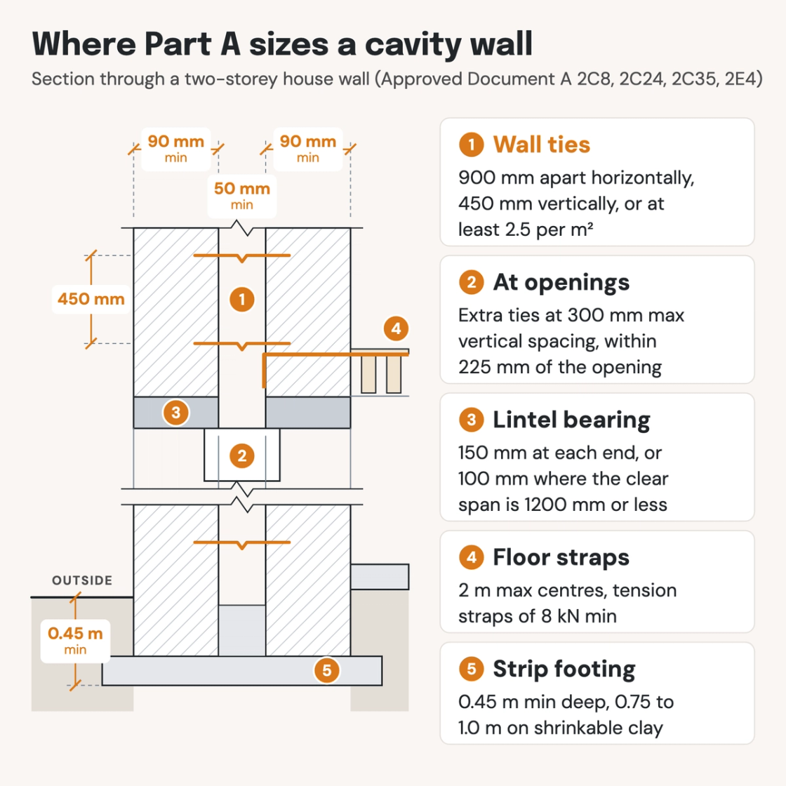
Check your set instantlyPart A of the Building Regulations covers structure: loading (A1), ground movement (A2) and disproportionate collapse (A3). Approved Document A sizes masonry for residential buildings up to three storeys without calculation. Cavity leaves are at least 90 mm, cavities 50 mm, and ties 900 by 450 mm apart. Lintels bear 150 mm; strip footings sit 0.45 m deep or more.
The Pirros Quality Management System can check the lintel bearings on every window head detail in your set and Revit model, instantly.
How to check the code requirements
Part A reaches a drawing set through the wall sections, window head details and foundation details. Check first that Section 2C covers the building at all. Then check each dimension on the sections against its paragraph.
- Confirm the building fits Section 2C. Up to three storeys, 15 m high and no taller than twice its least width (2C4). No floor over 70 m² between structural walls (2C14). Outside those limits, the walls are designed to the Section 1 standards instead.
- Dimension the cavity wall. Leaves 90 mm minimum and cavity 50 mm minimum (2C8). Add the two leaves and 10 mm, and check the sum against the Table 3 solid wall thickness.
- Space the ties. At 900 mm horizontally and 450 mm vertically, plus 300 mm vertical spacing within 225 mm of every opening, movement joint and verge (2C8). Take the tie length from Table 5 for the cavity width.
- Check every lintel bearing. 150 mm at each end, or 100 mm where the clear span is 1200 mm or less (2C24). A 1800 mm opening drawn with 100 mm bearings fails.
- Show the restraint straps. Tension straps tie the walls to each floor at 2 m maximum centres (2C35). Gables and eaves get straps at roof level unless the roof meets the 2C36 conditions.
- Take the footings deep enough. 0.45 m minimum to the underside, or 0.75 to 1.0 m on shrinkable clay (2E4). Read the width from Table 10 for the ground type and the load on the wall.
Section 2C sizes masonry walls only. Beams, frames and buildings outside its limits are designed to the Eurocodes, normally by structural engineers. Approved Document A is free on gov.uk. On a drawing set its dimensions sit on the wall section and its details. That is where an AI-powered quality management system reads them.
How Pirros checks the set
The Pirros Quality Management System reviews projects against code requirements, firm standards, and project specifications, then assigns, tracks, and resolves issues before they become RFIs or rework.
- Reads every sheet in your set against the codes you pick for the project: the Building Regulations and Approved Documents.
- Every finding names the sheet, the location and the section behind it.
- Findings are surfaced, never auto-applied. Your reviewer confirms, dismisses or escalates.
Requirements at a glance
| Element | Requirement | Section |
|---|---|---|
| Loading and ground movement | The building carries its combined dead, imposed and wind loads safely to the ground. It may not deflect, deform or move the ground enough to impair the stability of another building. Swelling, shrinkage or freezing of the subsoil, land-slip and subsidence must not impair its stability, as far as the risk can reasonably be foreseen. | Requirements A1, A2 |
| Disproportionate collapse | After an accident, the building must not collapse to an extent disproportionate to the cause. Since the 2004 edition, A3 applies to buildings of any height. | Requirement A3 |
| Two routes to compliance | Design any building to the Eurocodes and other references listed in Section 1. Or, for small buildings of traditional construction, size the elements from Section 2 without calculation. | Para 0.1 |
| Where Section 2C applies | Residential buildings of up to three storeys, 15 m high at most and no taller than twice their least width. Also small single-storey non-residential buildings, 3 m high and 9 m long or wide at most, and annexes 3 m high. Wind exposure can set a lower height limit. | Paras 2C1, 2C4, 2C16 |
| Floor area, wall size and floor span | No floor enclosed by structural walls on all sides over 70 m², and no floor without a structural wall on one side over 36 m². Walls no longer than 12 m between buttressing walls, piers or chimneys, and no higher than 12 m. Floor spans 6 m maximum. | Paras 2C14, 2C17, 2C23 |
| Solid wall thickness | At least 1/16 of the storey height. 190 mm for walls up to 3.5 m high and 12 m long, or up to 9 m high and 9 m long. Larger walls, up to 12 m, take 290 mm for the lowest storey, or the lowest two when both height and length exceed 9 m. Uncoursed stone or flint: 1.33 times that. | Paras 2C6, 2C7, Table 3 |
| Cavity walls | Each leaf at least 90 mm thick and the cavity at least 50 mm wide. The two leaves plus 10 mm must be no less than the solid wall thickness Table 3 gives for the same height and length. | Para 2C8 |
| Wall ties | 900 mm horizontal and 450 mm vertical spacing, or at least 2.5 ties per m². Extra ties at 300 mm maximum vertical spacing within 225 mm of openings, movement joints and roof verges. Austenitic stainless steel to BS EN 845-1, with the length from Table 5. | Paras 2C8, 2C19, Table 5 |
| Internal load-bearing walls | Half the Table 3 thickness, less 5 mm, except compartment and separating walls. In the lowest storey of a three-storey building, carrying both storeys above, at least 140 mm. | Para 2C10 |
| Lintels and loads on walls | Lintel bearing 150 mm, or 100 mm where the clear span is 1200 mm or less. Ground levels either side of a wall differ by less than four times its thickness. Combined dead and imposed load 70 kN/m maximum at the base of the wall. | Para 2C24 |
| Imposed loads assumed | Floors 2.00 kN/m². Roofs 1.00 kN/m² for spans up to 12 m, or 1.5 kN/m² for spans up to 6 m. Ceilings 0.25 kN/m² with a 0.9 kN concentrated load. | Para 2C15, Table 4 |
| Buttressing, openings and chases | A buttressing wall at least 1/6 of the supported wall’s height long. Below ground floor, only small holes for services and ventilation, 0.1 m² maximum at 2 m centres or more. Vertical chases no deeper than 1/3 of the wall or leaf thickness, horizontal ones 1/6 of the leaf. | Paras 2C26, 2C29, 2C30 |
| Restraint at floors | Walls strapped to floors above ground level at 2 m maximum centres, with tension straps of at least 8 kN declared strength. Some joist bearings and hangers in houses of up to two storeys, and concrete floors with 90 mm bearing, need no straps. A stair opening beside a supported wall is 3 m long at most. | Paras 2C35, 2C37 |
| Restraint at roofs | Gable walls strapped to the roof. Vertical straps at least 1 m long at eaves level, at 2 m maximum centres. They may be left out where the roof is pitched 15° or more, tiled or slated and locally proven against wind gusts. Its main members must then sit at 1.2 m maximum centres. | Para 2C36 |
| Strip foundation depth | At least 0.45 m to the underside, except on rock. On shrinkable clay, at least 0.75 m for low, 0.9 m for medium and 1.0 m for high shrinkage, and deeper near trees. | Para 2E4 |
| Strip foundation width and thickness | Width by ground type and wall load from Table 10. At 30 kN/m: 300 mm on medium dense gravel or sand and on stiff clay, 350 mm on firm clay. Concrete at least 150 mm thick, and footings centred under the wall. | Para 2E2, Table 10 |
| Consequence classes | Class 1: houses up to 4 storeys and agricultural buildings. Class 2a: for example flats, hotels and offices up to 4 storeys. Class 2b: for example flats and offices of 5 to 15 storeys, hospitals up to 3 storeys and car parks up to 6. Class 3: buildings beyond those limits. | Table 11 |
| Measures against collapse | Class 1: nothing beyond the A1 and A2 rules. Class 2a: horizontal ties, or floors anchored to walls. Class 2b: horizontal and vertical ties, or notional removal with collapse limited to 15% of the storey or 100 m², whichever is smaller. Class 3: a systematic risk assessment. | Paras 5.1, 5.3 |
These numbers are from Approved Document A, 2004 edition incorporating 2004, 2010 and 2013 amendments, which applies in England. The 2013 amendments moved the design references to the Eurocodes and revised the guidance on disproportionate collapse, wind maps and strip footings. Requirements A1 to A3 themselves did not change. Wales and Scotland have their own rules.