Curtain Wall Details: How Each Section Comes Together
Curtain wall details by location: slab edge, anchor, sill, head, jamb and parapet, with the fire safing, drainage and movement each one has to handle.

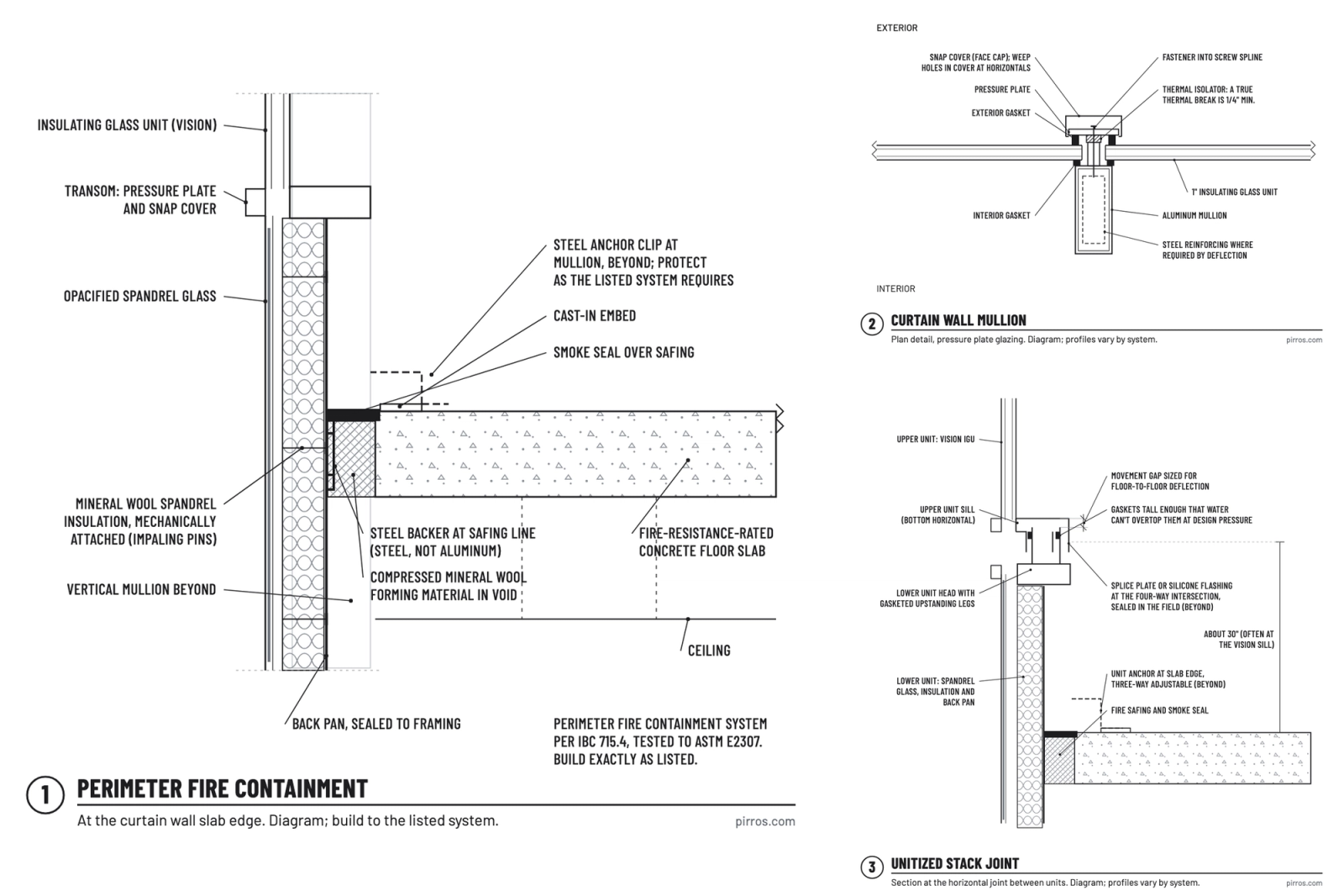
Curtain wall details show how a glass and aluminum wall that carries no floor loads hangs from the building and keeps out water, air and fire. A typical set covers the slab edge and anchor, the sill, head and jamb, a plan detail at the mullion and, on a unitized wall, the stack joint.
Each detail in the set has its own primary job: the slab edge carries the wall and stops fire between floors, the sill drains water, the mullion holds the glass and keeps heat out, and the stack joint takes the building's movement.
That's why most searches for curtain wall details name a place: the sill, the anchor, the slab edge, the parapet. This guide goes through the set location by location, what each detail has to show and what tends to go wrong there.
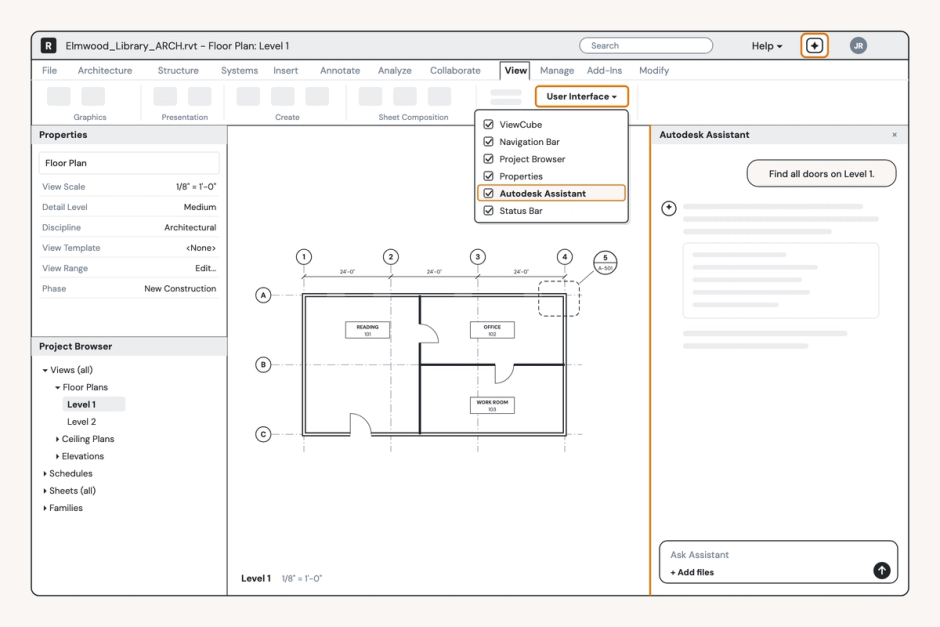
Drawing curtain wall details in Revit? Mira, the AI agent for Revit, can list the curtain wall corners in a model that still need a corner mullion.
What is a curtain wall?
A curtain wall is a thin wall, usually framed in aluminum and filled with glass, metal panels or thin stone. It's attached to the building structure but carries none of the floor or roof loads. It carries its own weight and the wind on it, and passes both to the structure, usually at each floor (WBDG: Curtain Walls, archived). Revit defines it the same way (Autodesk Revit Help: About Curtain Walls).
A storefront wall looks similar but works differently. It spans a single story, anchored at head and sill, and sits between structural members. Curtain wall runs past the slab edges, with its vertical mullions anchored to the structure. Drainage is also different: curtain wall drains each lite on its own, while storefront drains the whole elevation at the sill, which is why storefront usually stays at the ground floor.
Stick-built or unitized
The system type changes which details you draw.
- Stick-built. Mullions and glass go in piece by piece on site. Mullions usually run past two floors, with a combined gravity and lateral anchor at one floor and a lateral-only anchor at the other. A splice in the mullion lets it move vertically (WBDG).
- Unitized. Units are assembled and glazed in the factory, usually one story tall and 5 to 6 ft wide, then hung from the slab edge. Adjacent units mate at split mullions and at a horizontal stack joint (WBDG). Glazing in the shop means faster installation and better quality control (Kawneer: Curtain Wall Systems).
The glass is held one of three ways:
- A pressure plate fastened to the mullion clamps the glass against gaskets, under a snap-on cover.
- Structural silicone glazing bonds the glass to the frame.
- Interior dry glazing sets the glass from inside behind a removable stop. Each shows up differently in the mullion detail.
Curtain wall details by location
Slab edge and anchor
Most curtain wall sections cut here, through the floor where the wall passes the slab edge.
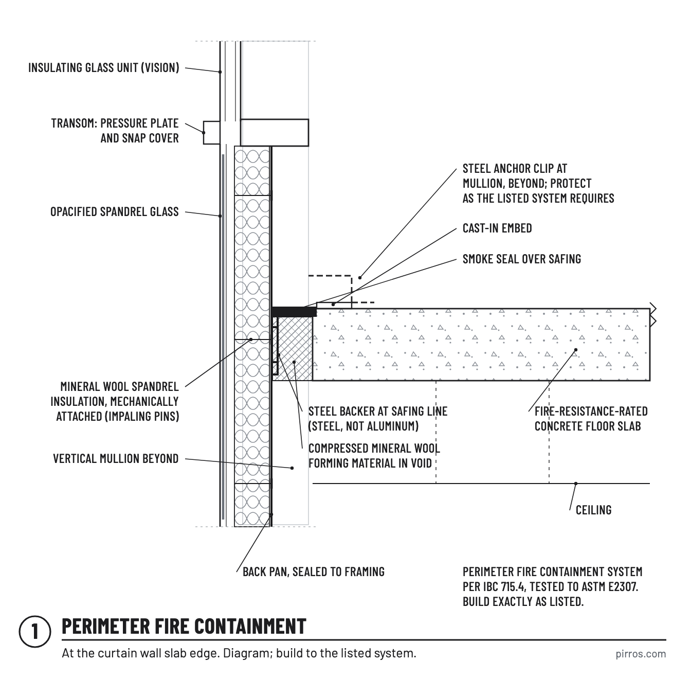
A curtain wall detail should show:
- The anchor. A clip or bracket ties the mullion to the slab edge or spandrel beam. Unitized anchors are usually proprietary, with three-way adjustment to take up construction tolerance and slab movement before the wall goes up (WBDG).
- The spandrel. The opaque band that hides the slab and ceiling space: opacified glass, a metal panel or a shadow box with a metal sheet at least 2 in behind the glass. Behind it sit insulation and a back pan, a sheet sealed to the framing that acts as the air and vapor barrier in cold climates.
- The perimeter fire barrier. The gap between the slab edge and the back of the wall is open from floor to floor. It gets mineral wool spandrel insulation, mechanically attached; a steel backer; mineral wool forming material compressed into the void; and a smoke seal on top (International Firestop Council: Perimeter Fire Containment).
Where a curtain wall meets a fire-resistance-rated floor, IBC Section 715.4 requires an approved perimeter fire containment system with an F rating at least equal to the floor's rating, tested to ASTM E2307 (2024 IBC, Chapter 7). E2307 checks whether the barrier stays in place as the wall and floor deflect in a fire (ASTM E2307). Where the floor isn't rated, Section 715.5 still requires the void to be filled. In high-rise buildings, among others, special inspection of the system is required (2024 IBC, Chapter 17).
Common fire safing mistakes at the slab edge, according to the International Firestop Council: the void is filled but part of the spandrel is left unprotected, so the wall fails and the safing falls out; insulation is glued instead of mechanically fastened; an aluminum backer melts where steel was needed; safing isn't compressed, so gaps open; fasteners from different listed systems get mixed; and the anchors are left unprotected. A tested assembly works only as built, so the detail should name the listed system it follows.
Our guide to fire-rated wall assemblies covers how listings work.
Sill and base
At the bottom of the wall, the detail shows a sill flashing with end dams and a back leg turned up into the glazing pocket, sloped to the outside and sealed to the adjacent wall's air and water barrier. Jamb flashings carry leakage down to it (WBDG).
Inside the frame, every horizontal drains. WBDG calls for weeps at least 3/8 in in diameter (or 5/16 by 3/8 in slots), usually three per horizontal, with the glass setting blocks kept clear of them. A curtain wall has no sill flashing at each opening the way a window does, so a leak at a frame corner runs to the interior or into the glass below. Watertight corners and clear drainage matter more here than anywhere else.
Head and parapet
The head detail mirrors the sill: a head flashing sloped out and sealed to the adjacent air and water barrier (WBDG). At the top of the building, that flashing ties into the roofing at the roof edge or parapet. One code difference from the floors: the IBC doesn't require a fire-resistant joint system where a curtain wall meets a roof slab or deck (Section 715.3).
Jamb and corner
At the sides, jamb flashings tie the curtain wall's air and water barrier to the wall beside it. Pressure plate glazing makes that tie-in easiest (WBDG). Anti-walk blocks at the jambs keep the glass from creeping sideways. At an outside corner, the two walls meet at a corner mullion; here's how to model a corner mullion in Revit.
Mullion plan detail
A plan cut through a vertical mullion shows how the glass is held and how heat is kept out.
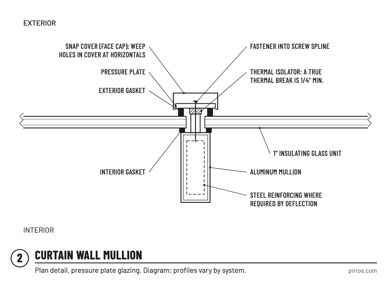
On a pressure plate system, the plate is fastened to the outside of the mullion and clamps the glass between gaskets, and a snap cover hides the fasteners. The gaskets also act as thermal and acoustic isolation, and water that gets past them leaves through weep holes in the cover. A thermal break separates the outer aluminum from the mullion inside. WBDG counts a separator of at least 1/4 in as a true thermal break; anything thinner is only thermally improved.
Mullions are the main wind-load members: transoms frame into them, so if the transoms are beams, the mullions are girders. A common deflection limit is L/175 for spans under 13 ft 6 in and L/240 + 1/4 in for longer ones (STRUCTURE: Fundamentals of Structural Curtainwall Design). Where a thin sightline is called for, a steel stiffener inside the hollow mullion provides stiffness.
Unitized stack joint
On a unitized wall, the stack joint is where one floor's units meet the next.
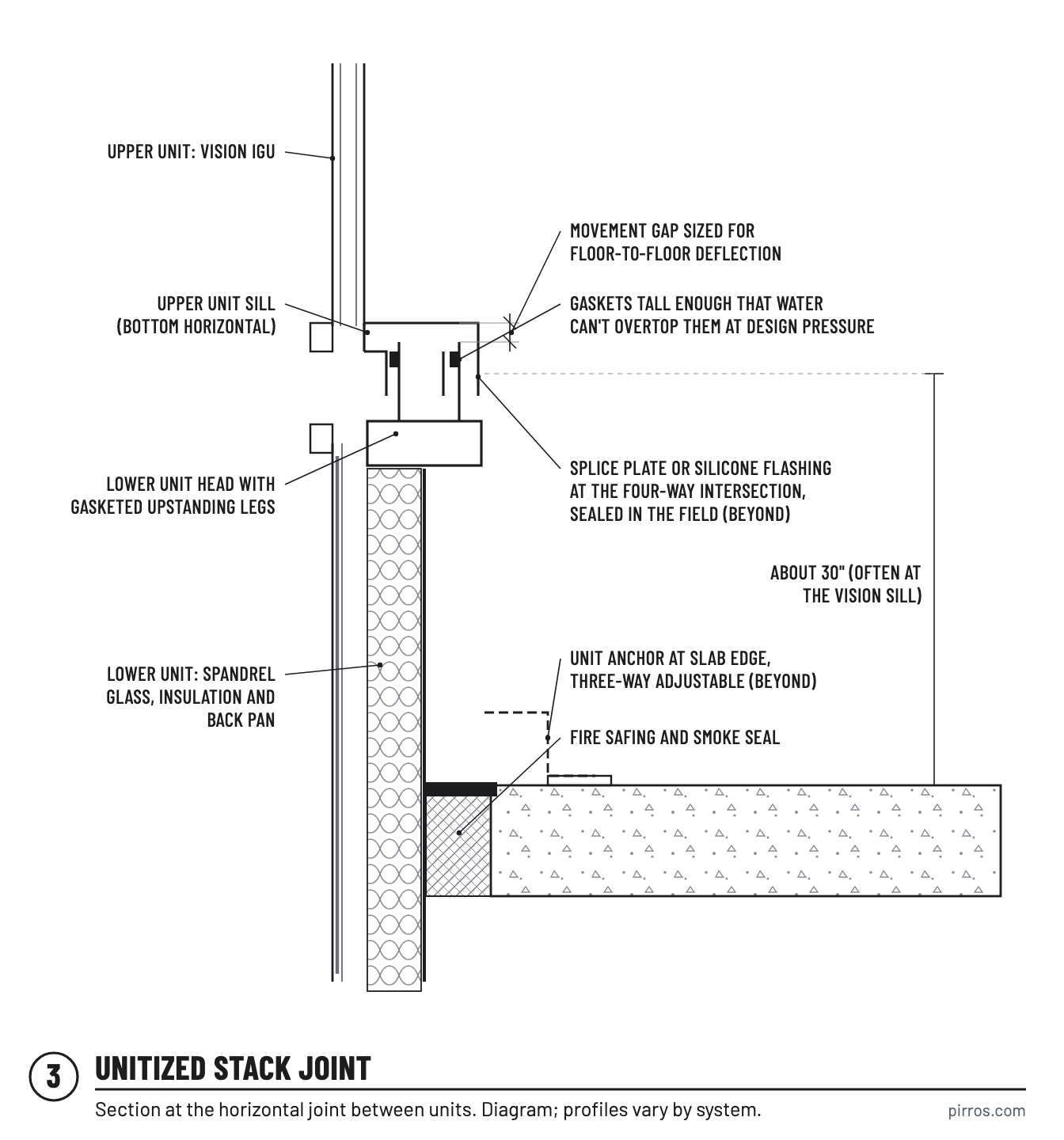
The top horizontal of each unit has gasketed legs that stand up into the bottom horizontal of the unit above. Where four units meet, the four-way intersection is sealed in the field, usually with a splice plate or silicone flashing across the top of the units. Many walls put the stack joint at the vision-glass sill, about 30 in above the floor, which keeps the joint easy to reach. The mating profiles are sized for the floor-to-floor deflection the joint has to take, and the gaskets are tall enough that water can't overtop them at the design pressure (WBDG).
Water, air and movement
Every detail above follows from two facts: seals leak, and buildings move.
Water. WBDG names three strategies. Face-sealed walls rely on perfect, continuous seals and should be avoided. Water-managed walls drain the glazing pocket. Pressure-equalized rainscreen walls also seal each glazing pocket off from its neighbors, so the pocket's pressure matches the outside and water isn't pushed in. Assume the outer seals will leak and design the drainage to cope (WBDG).
Movement. A curtain wall has to take slab edge deflection before and after it goes up, its own weight on the slab, live load, creep, construction tolerance, and drift from wind and earthquakes. Anchors absorb what happens before installation; the joints between units and the mullion splices take what happens after (STRUCTURE). Ask the structural engineer for slab deflection at installation, further deflection afterwards and interstory drift with load factors stated (STRUCTURE: Structure and Facade Coordination). When facade and structure movements clash, glass breaks.
Condensation. In cold climates, insulating the mullions in a spandrel area can cause condensation if room air reaches them, and condensate gutters must sit outboard of the back pan or they breach the air barrier.
Codes and tests the details point to
A curtain wall detail names the tests the system has to pass. The usual set:
| Test | What it checks | Where |
|---|---|---|
| ASTM E2307 | Perimeter fire barrier at the slab edge | Lab |
| ASTM E283 | Air leakage | Lab |
| ASTM E331 and E547 | Water penetration, steady and cyclic pressure | Lab |
| AAMA 501.1 | Water penetration under dynamic pressure | Lab or field |
| ASTM E1105 | Water penetration of the installed wall | Field |
| AAMA 501.2 | Hose check of the installed wall | Field |
| ASTM E330 | Structural performance under wind pressure | Lab |
| AAMA 501.4 and 501.6 | Interstory drift, static and dynamic | Lab |
WBDG recommends field testing a mock-up for every curtain wall, and testing air and water again at about 35% and 70% of installation and at completion (WBDG).
Drawing curtain wall details in Revit
In Revit, a curtain wall is a wall type. The defaults are Curtain Wall 1, Exterior Glazing and Storefront. Grid lines divide the wall into panels, and mullions sit on the grid lines. A mullion's shape comes from a 2D profile family, which can carry detail components that show only where the mullion is cut, at the Fine detail level (Autodesk Revit Help: About Mullion Profiles).
The details themselves are drawn one of two ways:
- A detail callout cut from the model shows the curtain wall as an underlay, with 2D detail components drawn over it. It updates when the model changes (Autodesk Revit Help: About Detail Views).
- A drafting view holds 2D linework only, tied to no model elements, so it can move from project to project (Autodesk Revit Help: About Drafting Views). That's why firms keep their typical curtain wall details as drafting views.
Name each typical by its condition: "Curtain wall sill, unitized, at slab on grade" finds itself; "Detail 7" never will. The manufacturer's typical details show the system. The firm's own version records the parts the manufacturer leaves out: the listed fire barrier, the flashing tie-ins and the air barrier transitions. Our guides to wall sections and typical details cover the rest of the set.
How Pirros and Mira help
Most firms have drawn a good slab-edge detail before. The trouble is finding it: it sits in a project from three years ago, named for the sheet it was on.
Pirros makes every detail your firm has drawn searchable by what it shows. Search "curtain wall sill" and Pirros finds sill details across past projects, with the approved typicals marked, and Pirros in Revit drags the one you pick into the open model. At David Baker Architects, that's how details get vetted: "We also use Pirros as a tool to vet details. Vetted details filter into our Revit template, and then back into Pirros," says Orrin Goldsby, an architect at DBA.
In the model, Mira, the AI agent for Revit, handles the repetitive checks. Type "List the curtain wall corners in this model that don't have a corner mullion yet." Mira only reads the model for this one: it lists each place where two curtain walls meet without a corner mullion, with the level and what sits there now, and changes nothing.
See your firm's curtain wall details in one place
Book a demo to see how Pirros finds, vets and places the details your firm has already drawn. Working in Revit right now? Try Mira free.