International Mechanical Code: What the IMC Requires and How to Check a Set
What the International Mechanical Code (IMC) covers, chapter by chapter, and its rules for ventilation, Type I hoods, fire dampers and machinery rooms.

The International Mechanical Code (IMC) is the International Code Council's model code for heating, ventilation, air conditioning, exhaust and refrigeration systems in buildings. It sets how much outdoor air each space needs, how commercial kitchen exhaust is built, where ducts need fire dampers, and when refrigeration equipment needs a machinery room.
The IMC is adopted in 47 states, the District of Columbia, Puerto Rico, Guam and the US Virgin Islands, according to the International Code Council. States and cities adopt it with their own amendments, and some still enforce an earlier edition. Before you design to a number, check which edition your jurisdiction uses and what it changed.
This guide covers what the IMC includes, then the requirements that most often involve both the mechanical engineer and the architect. Values are from the 2021 IMC; the changes in the 2024 and 2027 editions are near the end.
What the IMC covers
The IMC regulates the design, installation, maintenance, alteration and inspection of mechanical systems that are permanently installed to control the environment inside a building (Section 101.2).
Other codes pick up where the IMC stops:
- Fuel gas: gas piping, gas-fired appliances and their venting follow the International Fuel Gas Code (Section 101.2).
- Houses: detached one- and two-family dwellings and townhouses up to three stories above grade plane may follow either the IMC or the International Residential Code (Section 101.2, exception).
- Building construction: rated walls, shafts and the dampers in them are set by the International Building Code (IBC). IMC Section 607 repeats the IBC's damper rules under its own numbers.
For buildings more than two stories tall, the construction documents must show where mechanical systems penetrate, and how fire-resistance ratings and fireblocking are maintained (Section 110.1).
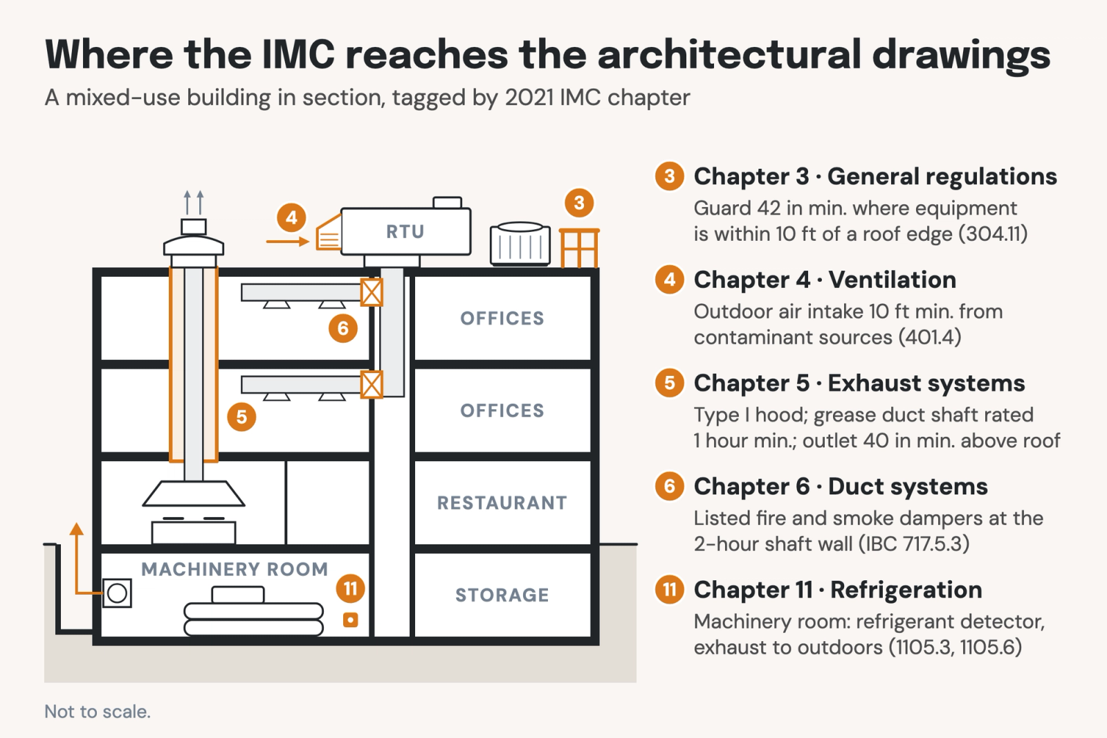
The 2021 IMC has 15 chapters. This guide covers the five that reach the architectural drawings most often:
- Chapter 3, General Regulations: equipment access, guards and condensate.
- Chapter 4, Ventilation: outdoor air rates.
- Chapter 5, Exhaust Systems: commercial kitchen hoods and grease ducts.
- Chapter 6, Duct Systems: fire and smoke dampers.
- Chapter 11, Refrigeration: refrigerant limits and machinery rooms.
The others cover administration and definitions, combustion air, chimneys and vents, appliances, boilers, hydronic and fuel oil piping, solar thermal systems, and the referenced standards (Chapter 15).
How the IMC uses ASHRAE, NFPA and UL standards
A standard the IMC cites becomes part of the code to the extent each section cites it, and where the two conflict, the code governs (Sections 102.8 and 102.8.1). Chapter 15 lists the edition of each.
The standards behind the sections in this guide are:
- ASHRAE 62.1, Ventilation for Acceptable Indoor Air Quality, from ASHRAE. The IMC's ventilation method follows it, and Section 403.3.1.1.2.3.2 lets you take one factor from its Appendix A.
- ASHRAE 15, Safety Standard for Refrigeration Systems, and ASHRAE 34, which classifies refrigerants by toxicity and flammability. Chapter 11 cites both.
- NFPA 96, the National Fire Protection Association's standard for ventilation control and fire protection of commercial cooking operations, cited in Section 507.1.
- UL 555, UL 555S and UL 555C, the test standards for fire dampers, smoke dampers and ceiling radiation dampers (Section 607.3.1).
The edition that applies is the one your adopted code names: the 2021 IMC names the 2019 editions of ASHRAE 62.1 and ASHRAE 15, though ASHRAE's current editions are 62.1-2025 and 15-2024.
Equipment access and clearances (Chapter 3)
Chapter 3 sets the space that mechanical equipment needs around it, and most of that space appears on the architectural drawings. Equipment has to be reachable for service and replacement without removing permanent construction or disabling a fire-resistance-rated assembly (Section 306.1).
The requirements architects most often have to draw are:
- Working space: a level space at least 30 inches deep and 30 inches wide in front of the control side of an appliance (306.1).
- Equipment rooms: a door and an unobstructed passageway at least 36 inches wide and 80 inches high (306.2).
- Roofs: where reaching the equipment means climbing more than 16 feet above grade, a permanent means of access, not a portable ladder (306.5).
- Guards: where serviceable equipment or a roof hatch sits within 10 feet of a roof edge that is more than 30 inches above the surface below, a guard at least 42 inches high, unless fall-arrest anchors to ANSI/ASSP Z359.1 are installed (304.11).
- Condensate: a drain from every cooling coil to an approved place, sloped at least 1/8 inch per foot, plus a secondary drain or overflow protection where an overflow could damage the building (307.2).
Ventilation rates (ASHRAE 62.1)
Every occupied space needs ventilation while it is occupied, either natural, through openings of at least 4 percent of the floor area, or mechanical, at the outdoor air rates in Section 403.3 (Sections 401.2, 401.3 and 402.2).
For mechanical ventilation, the breathing-zone outdoor air (Vbz) is a people rate times the number of people plus an area rate times the floor area (Equation 4-1). Table 403.3.1.1 gives both rates for each kind of space, along with the occupant density that sets the minimum number of people to design for. Typical rows include:
- Office spaces: 5 people per 1,000 square feet, 5 cfm per person and 0.06 cfm per square foot.
- Conference and meeting rooms: 50 people per 1,000 square feet, 5 cfm per person and 0.06 cfm per square foot.
- Dining rooms: 70 people per 1,000 square feet, 7.5 cfm per person and 0.18 cfm per square foot.
The table's categories are kinds of space, such as conference rooms, and not the IBC's occupancy groups.
Here is a worked example. A 2,000-square-foot conference room at 50 people per 1,000 square feet is designed for 100 people. Its breathing-zone outdoor air is 5 × 100 + 0.06 × 2,000 = 620 cfm.
The zone's outdoor air is Vbz divided by the zone air distribution effectiveness, Ez (Equation 4-2, Table 403.3.1.1.1.2):
- Cooling: cool air supplied from the ceiling has an Ez of 1.0, so the room needs 620 cfm.
- Heating: warm air supplied from the ceiling with a ceiling return has an Ez of 0.8, so the room needs 775 cfm. The Ez rises to 1.0 where the supply air is less than 15°F above room temperature and its supply jet reaches within 4.5 feet of the floor.
A single-zone rooftop unit serving only that room must deliver 775 cfm of outdoor air (Equation 4-3). Systems serving several zones add two more steps: occupant diversity, and a system ventilation efficiency (Ev) taken from Table 403.3.1.1.2.3.2 or from ASHRAE 62.1's Appendix A (Equations 4-5 to 4-8).
Three other Chapter 4 rules come up often in review:
- Exhaust: Table 403.3.1.1 also sets exhaust rates, such as 50 cfm per water closet or urinal in a public toilet room with continuous exhaust, or 70 cfm with intermittent exhaust. That air isn't recirculated (403.2.1).
- Demand-controlled ventilation: the people portion may follow actual occupancy, but outdoor air doesn't drop below the area portion while the building is occupied (403.3.1.3).
- Intakes: at least 10 feet from lot lines and from contaminant sources such as streets and loading docks, with exceptions (401.4).
Type I hood requirements (with NFPA 96)
A commercial cooking appliance needs a Type I hood if it produces grease or smoke, or if it is classed as medium, heavy or extra-heavy duty (Section 507.2). A Type I hood collects grease vapors and smoke and has a fire suppression system. A Type II hood handles heat, steam, odors and combustion products from appliances that don't produce grease (Chapter 2).
Under the Chapter 2 definitions, fryers and griddles are medium duty, underfired broilers and wok ranges are heavy duty, and anything burning solid fuel is extra-heavy duty. If one appliance under a hood needs Type I, the whole hood is Type I (507.1).
A Type I system runs from the cooking line to the roof, and each part has its own rules:
- The hood: a canopy hood overhangs the appliances by at least 6 inches on every open side, with its front lip no more than 4 feet above the cooking surface (507.4.1). It keeps 18 inches of clearance to combustible construction, unless that construction is protected as the section allows or the hood is listed for less (507.2.6).
- The exhaust rate: the heaviest-duty appliance under the hood sets it. For a wall-mounted canopy hood, that's 200 cfm per foot of hood for light duty, 300 for medium, 400 for heavy and 550 for extra heavy (507.5).
- The grease duct: No. 16 gage steel or No. 18 gage stainless steel with continuously welded, liquid-tight joints, carrying air at 500 feet per minute or more and sloping at least 1/4 inch per foot back toward the hood (506.3.1.1, 506.3.2, 506.3.4, 506.3.7).
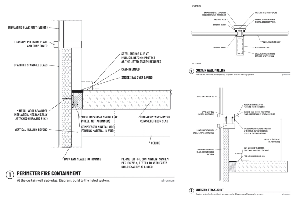
- The enclosure: where the duct passes through a ceiling, wall or floor, it runs in its own enclosure, rated at least 1 hour and at least as high as the assembly it penetrates. Fire and smoke dampers are not installed in grease ducts (506.3.11).
- The outlet: at least 40 inches above the roof, and 10 feet horizontally from air intakes or 3 feet above them (506.3.13.1, 506.3.13.3).
- Makeup air: about equal to the exhaust, and interlocked with the exhaust fan (508.1).
- Fire suppression: an automatic system for every appliance that needs a Type I hood (509.1). Under the International Fire Code, pre-engineered wet and dry chemical systems are listed to UL 300 and installed under NFPA 96 (IFC 904.13). Kitchens also need Class K portable extinguishers (IFC 906.4).
A hood listed to UL 710 follows its listing for size, position and exhaust rate instead of the code's numbers (507.1, Exception 1). NFPA 96 sets its own rules for clearances, duct enclosures and termination, so check the edition your fire official enforces alongside the IMC.
Fire damper requirements
A duct that crosses a fire-resistance-rated wall, floor or shaft usually needs a damper, and the type depends on the assembly it crosses (IBC Section 717; IMC Section 607). A fire damper closes on heat to restrict the passage of flame; a smoke damper closes on a signal from smoke detection; and a combination fire/smoke damper does both.
The fire-rated wall assemblies post explains how walls are rated, and the guide to the fire wall, fire barrier and fire partition explains which wall is which. The damper each one needs is:
- Fire walls: fire dampers. A fire wall that serves as a horizontal exit also needs a smoke damper (717.5.1).
- Fire barriers: fire dampers (717.5.2). They can be left out of walls rated 1 hour or less, outside Group H, in a building sprinklered throughout, where the system is fully ducted in steel of 26 gage or heavier from the air handler to the outlets and inlets.
- Shaft enclosures: listed fire and smoke dampers (717.5.3). They can be left out where steel exhaust subducts extend at least 22 inches up the shaft and a fan at the top runs continuously.
- Fire partitions, such as rated corridor walls: fire dampers, with several exceptions in sprinklered buildings (717.5.4).
- Smoke barriers: smoke dampers (717.5.5).
- Rated floors and ceilings: a fire damper at the floor line where a duct connects two stories without a shaft, and a ceiling radiation damper where a duct penetrates a rated ceiling membrane (717.6).
The damper itself has to match the assembly. Fire dampers are rated 1.5 hours in assemblies rated under 3 hours, and 3 hours in assemblies rated 3 hours or more (Table 717.3.2.1). Dampers with fusible links or internal operators need an access door at least 12 inches square or a removable duct section. The access point is labeled FIRE DAMPER, SMOKE DAMPER or FIRE/SMOKE DAMPER in letters at least 1/2 inch high (717.4).
The architect sets wall ratings on the life-safety plan and the mechanical engineer places dampers on the duct plans, so every damper check compares two sheets.
Refrigerant machinery rooms (ASHRAE 15)
A refrigeration system's refrigerant-containing parts must go outdoors or in a machinery room when the refrigerant in any one circuit exceeds the Table 1103.1 amount for the volume of the smallest enclosed occupied space (Sections 1104.2 and 1104.4). Chapter 11 is built on ASHRAE 15 and cites it in Sections 1101.6, 1105.8 and 1108.1, and refrigerants are classified under ASHRAE 34 (1103.1).
A refrigerant's safety group pairs a letter for toxicity (A lower, B higher) with a number for flammability (1 for none, 2L for lower, 2 and 3 for higher). Table 1103.1 lists each refrigerant's group and its limit in pounds per 1,000 cubic feet of the smallest enclosed occupied space: 13 for R-134a (A1), 26 for R-410A (A1), 22 for R-454B (A2L) and 4.8 for R-32 (A2L). Listed equipment holding 6.6 pounds or less needs no machinery room (1104.2, Exception 1), and institutional spaces use half the table amounts (1104.2.1).
Once a machinery room is required, the IMC sets what it must have:
- A refrigerant detector, with audible and visual alarms inside the room and outside each entrance (1105.3; IFC 608.9).
- Mechanical exhaust to the outdoors, discharged at least 20 feet from property lines and openings into buildings (1105.6, 1105.6.1). Normal ventilation is the larger of 0.5 cfm per square foot or 20 cfm per person (1105.6.3.1).
- Emergency exhaust that starts on the detector's alarm, sized at 100 times the square root of the refrigerant charge in pounds. A chiller holding 700 pounds needs about 2,650 cfm (1105.6.3.2).
- No open flames: no fuel-burning appliance drawing combustion air from the room, unless that air is ducted and sealed or a detector shuts the appliance off (1105.5).
- Exits: two exits or exit access doorways in rooms over 1,000 square feet, and in every machinery room, tight-fitting, self-closing doors that swing outward, with panic hardware (1105.9).
- Emergency switches: an off switch for the compressors, refrigerant pumps and automatic valves, and an on switch for the ventilation fans, outside the room next to its main entrance (1106.5; IFC 608.10).
- The enclosure: a refrigerant machinery room is an incidental use, so it needs a 1-hour separation or an automatic sprinkler system (IBC Table 509.1).
The move to A2L refrigerants changes some of this. The 2024 IMC requires comfort cooling systems that could leak into occupied spaces to use A1 or A2L refrigerants, except small listed equipment (2024 IMC 1104.3.1). It also sets how quickly an A2L machinery room's alarms and ventilation must respond (2024 IMC 1106.4).
What changed in the 2024 and 2027 editions
ICC publishes a new IMC every three years, and jurisdictions adopt each one on their own schedule, so a firm can have projects under several editions at once. The changes that touch this guide are:
- 2024: A1 or A2L refrigerants for most comfort cooling, and response times for A2L machinery room alarms and ventilation (Chapter 11).
- 2027: to go without a machinery room, a system must meet both Table 1103.1 and ASHRAE 15's effective dispersal volume charge limits. ASHRAE 62.1 Section 6.3 may set minimum outdoor air in occupancies other than Groups R-2, R-3 and R-4. Type I hoods get two compliance paths: a prescriptive one, and a hybrid that uses a UL 710 listing alongside some prescriptive rules. Chapter 6 is renamed Air Movement. These come from ICC's summary of the 2027 IMC.
When the mechanical and architectural sheets disagree
Most mechanical code problems in a set come from a change on one discipline's sheets that never reaches the other's. Common examples include:
- A room changes use, but its outdoor air doesn't. A storage room becomes a meeting room late in design, and the rooftop unit schedule still shows the outdoor air for storage.
- The kitchen equipment changes. The kitchen consultant adds a fryer under a hood scheduled as Type II, and nobody updates the hood, the duct or the suppression system.
- A wall picks up a rating. A corridor wall or shaft becomes rated on the life-safety plan after the ductwork is laid out, so no damper is shown where the duct crosses it.
- The chiller changes. A different chiller or refrigerant raises the charge, but the machinery room's emergency exhaust fan is still sized for the old one.
- Two editions appear in one set. The mechanical general notes cite the 2018 IMC while the code sheet cites the 2021.
None of these issues come from engineers not knowing the code. They happen because two disciplines, often two firms, draw against each other's sheets, and the sheets keep changing until the set goes out.
Across a firm, the same misses repeat from project to project. Mechanical notes and schedules are copied from the last job, with its edition and assumptions still in them, and the code check happens once, before permit. What helps is a building code analysis that names the IMC edition, and a check of the whole set, both disciplines, each time it changes.
Check the set against the IMC
Pirros's AI-powered Quality Management System reviews Revit models and drawing sets against the codes you select for each project, along with your firm's standards and the project specifications. The IMC is among the codes you can select, and Pirros processes code books centrally, so nobody uploads one. It reviews every sheet in a single run, mechanical sheets included.
Every code finding names the sheet, the location and the severity, and links to the clause it rests on. Findings are surfaced, never applied: your reviewer confirms, dismisses or escalates each one, and a licensed professional still signs the drawings.
At Number TEN Architectural Group, a review against the current building code surfaced sloped glazing and safety glass requirements that had been omitted from a set about to go out to bid. As Trent Piazzoni, Associate and Project Architect, puts it: "This platform can reinforce that process by consistently highlighting relevant items that may warrant another look."
Ordinarily, a Revit family for a hood, chiller or damper is modeled by hand from the manufacturer's cut sheet. Mira, Pirros's AI agent for Revit, can build it from the cut sheet. Attach the PDF and ask:
"Turn this cutsheet into a family."
Mira reads every page with drawings or tables, asks which model you want if the sheet covers several, and shows a table of each dimension with the page it came from, along with clearances and services such as duct connections. It points out anything the sheet doesn't give and every value it had to estimate, and it waits for your go-ahead before it builds the family. Mira builds the family; it doesn't check it against the code.
Read more about Pirros for MEP engineers. Try Mira free, or book a demo to see what a review finds in one of your live sets.